

Creates rows of parking stalls within a lot boundary - closed polylines/shapes or lines drawn on the physical, access and entrance boundary layers/levels portray certain parking lot characteristics. See Supported CAD Element Types, Properties -> Boundary Layers.
This tool uses the Perimeter Layout selected in the Stall Layout section of the Parking Standards tab in the Design Parameters -> Parking Standards dialog box to generate the perimeter rows along the physical boundary layer/level lines. The Interior Layout selected in the Stall Layout section is similarly used to generate the interior rows of the parking lot up to access boundary layer/level lines.
A lot boundary can be drawn with lines and arcs. This tool also supports the following element types in AutoCAD and MicroStation:
AutoCAD: Lines, arcs, polygons, closed polylines, polylines with lines and arcs. See AutoCAD help for information on creating polygons and closed polylines.
MicroStation: Lines, arcs, polygons, shapes, complex shapes and closed complex chains that contain line and arc segments. See MicroStation help for information on creating complex shapes/chains.
Note: physical, access, and entrance lines must touch or overlap before ParkCAD can work with them.
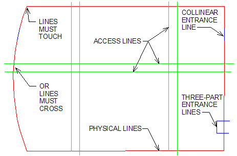
Lot Boundary drawn with Physical, Access, and Entrance lines
See Overview -> Row Properties for descriptions of the buttons used in this tool’s dialog box.
To use this tool you must have previously drawn a lot boundary using physical, entrance, and/or access boundary lines with CAD tools to create your parking lot within.
|
Generate Lot from Boundary |
or
Note: If you selected a design in step 2 above, you will need to save the changes to the parking design (see To Save a Design Iteration). Hint: You can make the rows parallel to the lot boundary sides by clicking Snap to Side. Move your mouse around the lot boundary to make the rows parallel to each side the mouse is closest to – the circle will change color when the mouse is closest to that side - See Setting Row Rotation Angle With Snap to Side below: |
Use this tool to have ParkCAD generate multiple lots automatically to determine the ideal stall count for a given lot boundary. Each lot is based on the current parking standard's selected Interior and Perimeter layouts (as shown in the Generate Lot dialog box) and combinations of snapping the interior rows to aisles and varying interior row rotation angles. This procedure assumes that a lot boundary has been selected and the Generate Lot dialog box is displayed.
In the Generate Lot dialog box, click  Maximize Stall Count. The following dialog box displays:
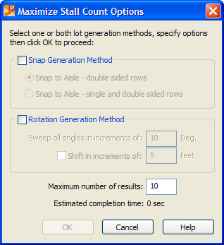
Maximize Stall Count Options
Select one or both of the lot generation methods:
Snap Generation Method: Selecting this option enables the Snap to Aisle ability of the interior rows snapping to doubled sided rows or snapping to single and double sided rows. (The latter option should generate twice as many lot results.)
Rotation Generation Method: Selecting this option enables the rotating of the interior rows to generate lot results.
Note: A shift distance greater than one half of the module width produces redundant entries in the results list. Therefore please specify a shift distance less than one half of the module width. For example, if your module width is 60 feet and you specify a shift distance of 12 feet you will get 5 unique rotation results for each shift increment in the results table. Also note that if you choose to display a small number of results these results may still not show up in the list.
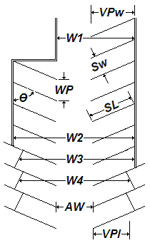
A complete module is one access aisle servicing a row of parking on each side of the aisle. W2 in the image below is an example of a complete module:
Specify the number of results to display then click OK. The following dialog box displays:
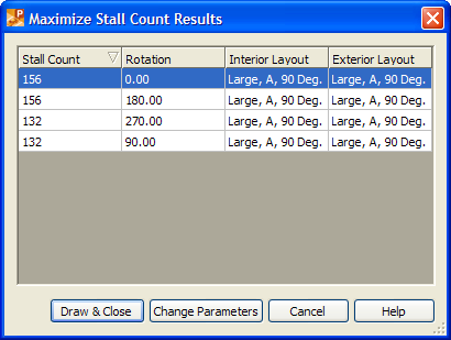
Maximize Stall Count
In the Maximize Stall Count Results dialog box, select a result to preview the lot in the drawing.
(Optional) Click Change Parameters to return to the Generate Lot dialog box, change layout and other settings then repeat the procedure from step 1. In this manner, the results from each use of the Maximize Stall Count tool will be added to the previous results.
(Optional) Click Cancel to return to the Generate Lot dialog box, change layout and other settings then repeat the procedure from step 1. In this manner, the results will be not be cumulative with each use of the Maximize Stall Count tool.
Preview the results in the drawing as desired then select the most appropriate result then click Draw & Close to draw the selected result in the drawing and return to the Generate Lot dialog box.
 Setting Row Rotation Angle With Snap to Side
You can make the rows parallel to the boundary sides by clicking Snap to Side. Move your mouse around the boundary to make the rows parallel to each side the mouse is closest to – the circle will change color when the mouse is closest to that side - See figures.
|
Highlighted circles with Snap to Side on (Access Boundary shown) |
Line drawn from pick point with Snap to Side off (Access Boundary shown) |
|
Highlighted circles with Snap to Side on (Physical Boundary shown) |
Rotating Rows from pick point with Snap to Side off (Physical Boundary shown) |

You can make the rows start against the polygon/shape side by using Snap to Side and Snap to Aisle while shifting the lot into position. See figures:
|
Shifting with Snap to Aisle on – Single Sided Row (Access Boundary shown) |
Shifting with Snap to Aisle on – Double Sided Row (Access Boundary shown) |
Entrance lines allow the user to define entrances and exits in lot boundaries. Entrance lines can be single collinear lines or three-part lines. Entrances can also be drawn with polylines, shapes, complex shapes or complex chains as long as there are three linear segments inside or crossing the physical lot boundary. Ensure that entrance lines do not extend into the lot beyond the perimeter row aisle. The end islands of perimeter rows are drawn parallel to three-part entrance lines. The end islands of perimeter rows are drawn perpendicular to collinear entrance lines. Entrances in arc boundaries must be collinear arcs. See the following figures:
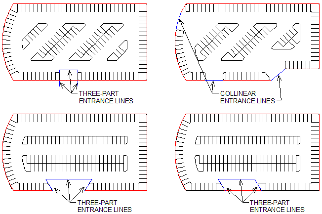
Example lots with Entrance Lines
See also: Generate Row From Points, Row Generation.
Examples of how not to draw Lot Boundaries:
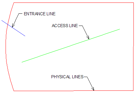
Access lines must cross both sides of the Physical boundary lines
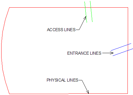
Access lines must cross both sides of the Physical boundary lines
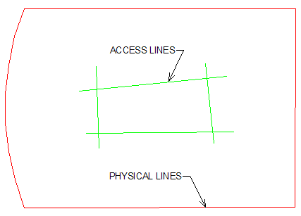
"Islands" or "Holes" are not supported (see Edit Exclusion instead)
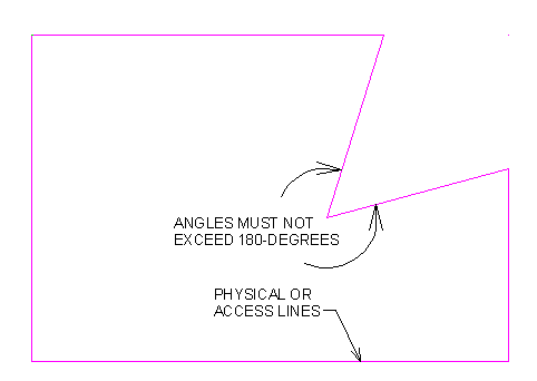
Concave boundaries are not supported