ParkCAD 5.0 Help
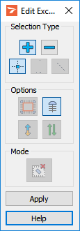
Edit Exclusion
Add and remove access and physical exclusion boundaries to/from lots. Exclusions can be added one at a time so that options can be set separately for each exclusion or they can be grouped into one selection set so that options can be set the same for each exclusion.
ParkCAD interprets the user drawn lines on the Exclusion Boundary Layer/Levels when adding exclusions. There are two types of exclusion boundaries - physical and access:
Boundaries drawn on the Physical Exclusion Boundary Layer/Level designate building walls, curbs, etc. (lines you don’t want vehicles to drive across). Aisles or rows are created on the outside of the physical exclusion boundary using the Perimeter Layout selected in the Design Parameters -> Parking Standards dialog box.
Boundaries drawn on the Access Exclusion Boundary Layer/Level designate aisles, driveways, etc. (lines vehicles can drive across).
An exclusion boundary can be drawn with lines however arcs cannot be used in any part of an exclusion boundary. This tool also supports the following element types in AutoCAD and MicroStation:
AutoCAD: Polygons, closed polylines, or polylines and lines. See AutoCAD help for information on creating polygons and closed polylines.
MicroStation: Shapes, complex shapes and closed complex chains that only contain line segments. See MicroStation help for information on creating complex shapes/chains.
An access exclusion must be drawn on the Access Exclusion Boundary Layer/Level before it can be added to a Lot with this tool. See Properties -> Exclusion Boundary Layers/Levels.
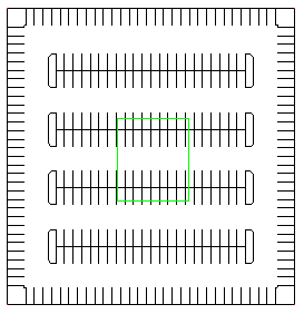
Lot with Access Exclusion Boundary drawn
|
Edit Exclusion - Add Access Exclusion |
See the Access Exclusion Example below. Access Exclusion Options
|
The access exclusion in this example lot was added to the lot with Edit Exclusion. The Bordering End Islands option was used to create islands on the rows that were cut off by the access exclusion.
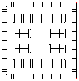
Lot with Access Exclusion added
A physical exclusion must be drawn on the Physical Exclusion Boundary Layer/Level before it can be added to a lot with this tool. See Properties -> Exclusion Boundary Layers/Levels.
Lot with Physical Exclusion Boundary drawn
|
Edit Exclusion - Add Physical Exclusion |
See Physical Exclusion Example below. Physical Exclusion Options
|
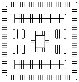
These drawings illustrate the use of two different option combinations on the same base lot and physical exclusion boundary. The example on the left was created by adding the exclusion boundary with the  Bordering End Island option only. The example on the right was created by adding the exclusion boundary with the
  Generate Rows and Bordering End Island options.
|
Lot with Physical Exclusion added |
Lot with Physical Exclusion added - with Perimeter Row |
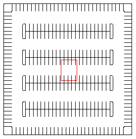
This tool is used to remove exclusions from lots. The user drawn exclusion boundary will be left in the drawing so that it may be edited with CAD tools.
|
Edit Exclusion - Remove Exclusion |
|
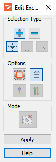
This tool is used to change the Options that govern the display of the Exclusion.
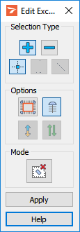
Click  Edit Exclusion on the ParkCAD Edit flyout or ParkCAD Edit toolbar if it is not already the current editing tool.
In the drawing, select the physical exclusion(s) or access exclusion(s) that you want to edit.
In the Edit Exclusion dialog box, set Options as desired to preview the exclusion(s).
Click Apply.
Repeat steps 2 to 4 or right-click to end this tool.

 Swap Flows: Toggle this option to change the open direction of angled stalls. This setting is used to reverse the traffic flow direction between the rows. It can be used with layouts that employ angles other than 90 degrees.
 Two-Way Aisles: Toggle this option to set the aisle distance to either AW (One-Way) or AW (Two-Way). When rows are snapped to this row or aisle construction lines are being drawn, they will be placed at the aisle distance as defined by the layout of the current parking standard.
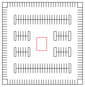
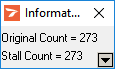
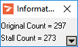
 Remove Exclusion. The Information dialog box will update to show the Stall Counts.