GuideSIGN Plus 2024 Help
This feature is not available in GuideSIGN.
Allows a sign assembly to be created. You can add and delete sign groups, arrange the signs in a sign group, insert standard signs and user-defined signs, set sign assembly options, and specify sign data. For information on the basic steps of creating a sign assembly and placing in into the sign plan drawing, see Creating a Sign Assembly: Basic Steps.
Click ![]() Create Sign Assembly on the GuideSIGN Plus toolbar or ribbon. A dialog box similar to the following example displays (for detailed information on the dialog box, see Tools -> Create Sign Assembly):
Create Sign Assembly on the GuideSIGN Plus toolbar or ribbon. A dialog box similar to the following example displays (for detailed information on the dialog box, see Tools -> Create Sign Assembly):
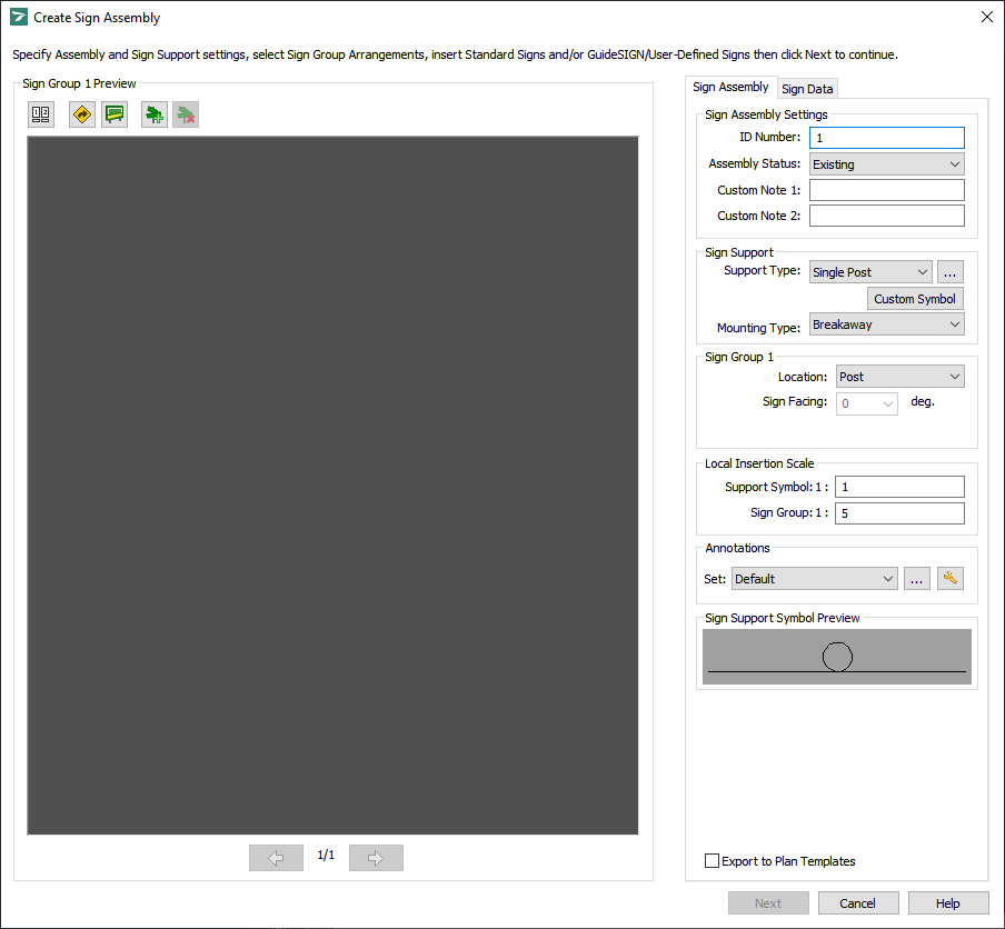
Create Sign Assembly
To modify the sign assembly ID number automatically assigned by GuideSIGN Plus, type the desired value in the ID Number box.
Note: To have GuideSIGN Plus assign the next consecutive number to each new sign assembly, clear the Reuse Available Sign Assembly ID check box located in the General category of ![]() Program Settings (see Program Settings - Plan -> General Category: Reuse Available Sign Assembly ID).
Program Settings (see Program Settings - Plan -> General Category: Reuse Available Sign Assembly ID).
In the Assembly Status list, select the desired sign assembly status.
(Optional) In the Custom Note 1 and Custom Note 2 boxes, type any notes relevant to the sign assembly.
Under Sign Support, in the Sign Support Type list, select the desired sign support type for the sign assembly. As you change the sign support type, the sign support symbol preview will update accordingly.
In the Mounting Type list, click the desired mounting type for the sign assembly.
Note: Mounting types will only be available if you select Single Post, Double Post, or Triple Post in the Sign Support Type list at step 5.
Under Sign Group, In the Location box, specify the location and then the Sign Facing angle for the sign group respectively.
Note: The contents of the Location list depend on the sign support type (see step 5 above).
(Optional) To override the scale values from Program Settings -> General, specify the desired values under Local Insertion Scale, in the Support Symbol and Sign Group boxes.
Select an Annotations Set to specify how the annotations will be placed around the sign groups.
(Optional) To select a sign group arrangement from the list of available preset arrangements, click ![]() Select Sign Group Arrangement. The Select Sign Group Arrangement dialog box displays. For information on selecting a sign group arrangement, see Selecting a Sign Group Arrangement. After you select the desired sign group arrangement, click OK to return to the Create Sign Assembly dialog box which will display as in the following example:
Select Sign Group Arrangement. The Select Sign Group Arrangement dialog box displays. For information on selecting a sign group arrangement, see Selecting a Sign Group Arrangement. After you select the desired sign group arrangement, click OK to return to the Create Sign Assembly dialog box which will display as in the following example:
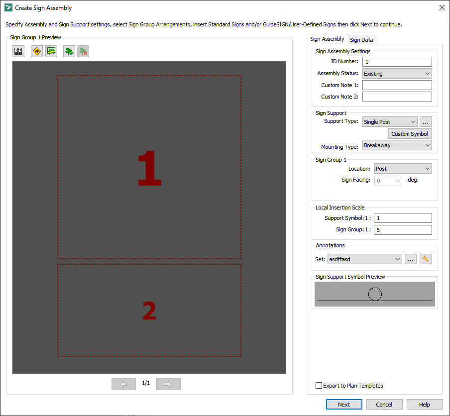
Create Sign Assembly - Sign group arrangement selected
To replace a box in the sign group arrangement with a sign, click the desired box, and then click ![]() Replace Sign, or simply double-click the box. The Replace Standard Sign dialog box displays. If you want to replace a box in the sign group arrangement with a user-defined sign, click
Replace Sign, or simply double-click the box. The Replace Standard Sign dialog box displays. If you want to replace a box in the sign group arrangement with a user-defined sign, click ![]() Switch to User-Defined Sign in the lower-left corner of the Replace Standard Sign dialog box. For information on replacing a box in the sign group arrangement with a sign, see Replacing a Sign. After you select the sign with which you want to replace the selected box, click OK to return to the Create Sign Assembly dialog box which will display as in the following example:
Switch to User-Defined Sign in the lower-left corner of the Replace Standard Sign dialog box. For information on replacing a box in the sign group arrangement with a sign, see Replacing a Sign. After you select the sign with which you want to replace the selected box, click OK to return to the Create Sign Assembly dialog box which will display as in the following example:
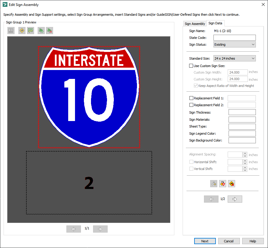
Create Sign Assembly - A box in the sign group arrangement replaced with a sign
To insert a standard or user-defined sign into the sign group, click ![]() Insert Standard Sign or
Insert Standard Sign or ![]() Insert User-Defined Sign respectively. The Insert Standard Sign or Insert User-Defined Sign dialog box displays. For information on selecting and inserting a standard or user-defined sign, see Inserting a Standard Sign or Inserting a User-Defined Sign respectively. After you select the sign to insert into the sign group, click OK to return to the Create Sign Assembly dialog box which will display as in the following example:
Insert User-Defined Sign respectively. The Insert Standard Sign or Insert User-Defined Sign dialog box displays. For information on selecting and inserting a standard or user-defined sign, see Inserting a Standard Sign or Inserting a User-Defined Sign respectively. After you select the sign to insert into the sign group, click OK to return to the Create Sign Assembly dialog box which will display as in the following example:
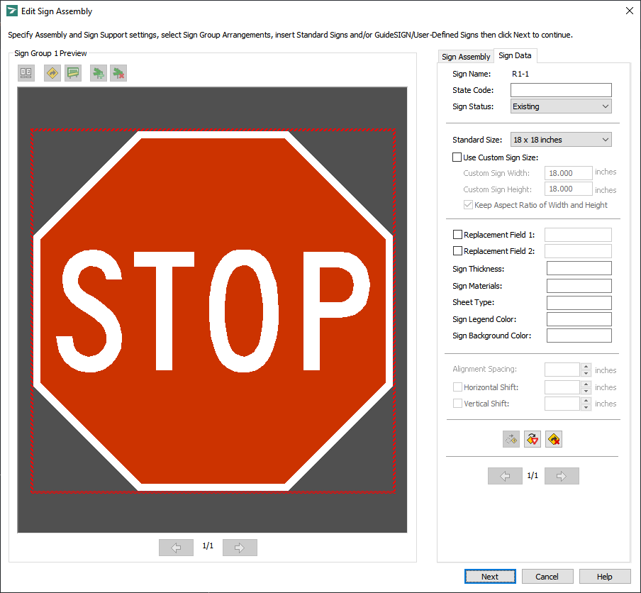
Create Sign Assembly - A sign inserted into the sign group
To select and insert more signs into the sign group, repeat the operations described above in this step.
Note: If you select a sign group arrangement after inserting one or more signs into the sign group, all the signs that were previously added to the sign group will be deleted.
(Optional) If there is more than one sign in the sign group, you can arrange/re-arrange the signs by selecting a particular sign, then clicking ![]() Move Sign, and then moving the sign to the desired location (see Moving a Sign).
Move Sign, and then moving the sign to the desired location (see Moving a Sign).
(Optional) To replace any of the signs displayed in the sign group preview, click the sign that you want to replace with a standard or user-defined sign, and then click ![]() Replace Sign, or simply double-click the sign, and then, in the Insert Standard Sign or Insert User-Defined Sign dialog box that will open, select the sign with which you want to replace the current sign (see Replacing a Sign).
Replace Sign, or simply double-click the sign, and then, in the Insert Standard Sign or Insert User-Defined Sign dialog box that will open, select the sign with which you want to replace the current sign (see Replacing a Sign).
(Optional) To delete a sign or box, select it in the sign group preview area, and then click ![]() Delete Sign (see Deleting a Sign).
Delete Sign (see Deleting a Sign).
To specify the state code for the selected sign, click the Sign Data tab, and then type an appropriate state code in the State Code box.
Note: The State Code box is available only if a standard sign is selected in the sign group preview area.
To specify the status of the selected sign, click the desired status in the Sign Status list.
(Optional) To modify the size of the selected sign while retaining the original width-to-height ratio, select the Use Custom Sign Size check box, make sure that the Keep Aspect Ratio check box is selected, then type the desired width or height value in the Custom Sign Width or Custom Sign Height box respectively, and the value in the other box will update accordingly. To edit the Custom Sign Width and Custom Sign Height values independently, clear the Keep Aspect Ratio check box, and then type the desired width and height values in the Custom Sign Width and Custom Sign Height boxes respectively.
To specify custom text for the selected sign, select the Replacement Field 1 and Replacement Field 2 check boxes, and then type the desired text in the corresponding boxes. The text specified in the replacement fields can be included in the report on the sign assembly (see Generating a Report).
To modify the alignment spacing between the selected and neighboring signs, type or select the desired value in the Alignment Spacing box. The sign group preview will update accordingly as you specify new values.
To shift the selected sign horizontally and/or vertically, select the Horizontal Shift and/or Vertical Shift check box(es), and then type or select the desired value(s) in the corresponding box(es) on the right.
To add another sign group to the sign assembly, click ![]() Add Sign Group, and then repeat steps 2 through 18.
Add Sign Group, and then repeat steps 2 through 18.
Note:
(Optional) To delete a sign group, navigate to it by clicking ![]() Previous Sign Group and
Previous Sign Group and ![]() Next Sign Group, and then click
Next Sign Group, and then click ![]() Delete Sign Group (see Deleting a Sign Group).
Delete Sign Group (see Deleting a Sign Group).
Note: If there is only one sign group present, it can not be deleted, so in this case ![]() Delete Sign Group will be dimmed:
Delete Sign Group will be dimmed: ![]() .
.
After you create a sign assembly, click Next to place the sign support symbol in the sign plan drawing (see Tools -> Create Sign Assembly -> Place Sign Support Symbol).