In This Topic
Turn simulations are generated using the current vehicle, program settings, and properties.
To Generate a Forward Maneuver:
Note: These instructions are generic for creating forward maneuvers with all SmartPath Tools. See the section on each SmartPath Tool for information specific to each SmartPath Tool. For instructions on how to generate reverse maneuvers, see To Generate a Reverse Maneuver.
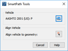
- Click one of the SmartPath Tools on the toolbar or ribbon. The following dialog box displays:

Note: The Align Vehicle section is not available for the Generate 3D Arc Path tool.
- Align vehicle to geometry or skip to step 3.
Expand steps:
- In the SmartPath Tools dialog box, click
 Align vehicle to Geometry.
- In the drawing, pick an element (line, arc, or polyline/complex chain).
- Pick a point to set the direction of travel.
- Pick a start point.
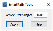
- If you did not align the vehicle to geometry at step 2, move the mouse in an arc around the front of the vehicle, and then click to set the desired Vehicle Start Angle value, or type the desired value in the dialog box and then click Apply. This sets the starting angle of the vehicle and its subsequent vehicle parts.

- (Optional) To set the articulating angles of the trailers in a multi-part vehicle:
Expand steps:

- Click inside the wheelbase of a trailer.
- Move the mouse pointer in an arc behind the trailer to rotate it.
- Click to set the desired angle.
- (Optional) Move the vehicle to a new start position.
Expand steps:
At any time before the first section is generated, click inside the wheelbase of the vehicle’s first part, move the vehicle to the new start position, and then click to set the new start position. The articulating angles will be retained.
- Set the Speed, Radius Type, and other various SmartPath Tools options depending on the type of simulation being generated.
- Move the mouse to the desired endpoint of the section, and then click to generate the section.
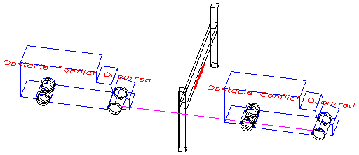
- The user drawn elements on the Obstacles Layer/Level are evaluated for conflicts with the vehicle body and body clearance envelopes of the turn simulation (see Properties -> Conflict Analysis Category).
Examples

2D conflict analysis example (the portions of user drawn elements that conflict with the turn simulation are denoted in red)

3D conflict analysis example (the portions of user drawn elements that conflict with the turn simulation are denoted in red)
- Repeat step 8 until the desired maneuver is completed. There is no limit to the number of sections in a simulation.
- Click a different SmartPath Tool button at the top of the dialog box to switch to a different maneuver type.
- Right-click to stop generating the simulation and close the SmartPath Tools dialog box.
See Also


 Align vehicle to Geometry.


