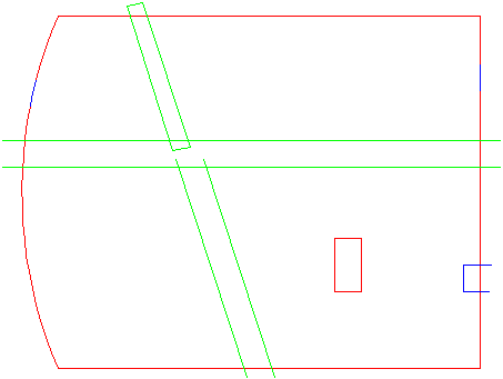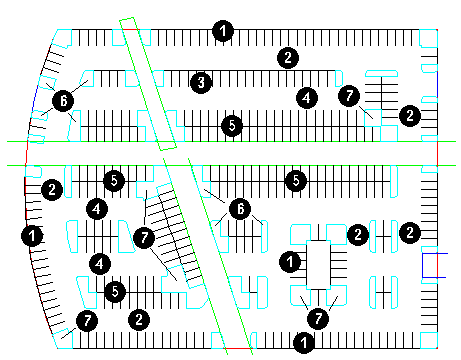

ParkCAD's generation tools create lots and rows which contain parking stalls by interpreting the user's CAD drawing. This section describes the elements that make up the drawn CAD lot and exclusion boundaries and the ParkCAD created lots, rows, and stalls. Each section has a list of relevant elements and a drawing that follows to illustrate each type of element:
Lot BoundariesA lot boundary can be drawn with lines and arcs. This tool also supports the following element types in AutoCAD and MicroStation: AutoCAD: Polygons, closed polylines, polylines with lines and arcs, lines, arcs or lines and arcs. See AutoCAD help for information on creating polygons and closed polylines. MicroStation: Polygons, shapes, complex shapes and closed complex chains that contain line and arc segments. See MicroStation help for information on creating complex shapes/chains. The figure below contains examples of the following lot and entrance boundaries:
Note: ParkCAD 5.0 does not scan for geometry on the PCENTRANCE layer after the lot is generated. The user is encouraged to use the Entrances tool to create and manage entrances. |
Exclusion BoundariesAn exclusion boundary can be drawn with lines however arcs cannot be used in any part of an exclusion boundary. This tool also supports the following element types in AutoCAD and MicroStation: AutoCAD: Polygons, closed polylines, or polylines and lines. See AutoCAD help for information on creating polygons and closed polylines. MicroStation: Shapes, complex shapes and closed complex chains that only contain line segments. See MicroStation help for information on creating complex shapes/chains. The figure below contains an example of each of the two types of exclusion boundaries:
|

Drawn CAD elements to represent a parking lot design
ParkCAD generates perimeter rows along physical lot boundaries using the Perimeter Stall Layout. The perimeter row's aisle width determines the interior boundary (see figure below). Interior rows are generated inside the interior boundary (similar to an access lot boundary) using the Interior Stall Layout. The stall layouts are set in Design Parameters -> Parking Standards under Stall Layout. Every row generated by ParkCAD is accompanied by an aisle.
The following drawings illustrate how interior rows are generated by ParkCAD when a lot is created. Note that the interior boundary is not drawn by the user or by ParkCAD - the line shown in the example is for illustrative purposes only.
|
Physical Lot Boundary |
Interior Boundary formed inside the Perimeter Layout Row Aisles |
In the example on the left, the interior rows do not entirely fill the interior boundary because there is not enough space to support another single sided or double sided interior row based on the dimensions of the interior stall layout.
|
Interior Layout Rows generated in the Interior Boundary |
Interior Layout Rows generated in the Interior Boundary |
The following lot was created using the above lot and exclusion boundaries as a starting point and then edited to achieve the final results.

ParkCAD created Lot from drawn CAD elements
Rows in ParkCAD lots are created based on the dimensions in the stall layouts in the current parking standard. ParkCAD uses two types of stall layouts: Perimeter and Interior to generate rows of stalls in lots. These stall layouts are used to create rows when interpreting the user's CAD drawing: perimeter rows are created along physical boundaries while interior rows are created up to access boundaries inside the lot. When these rows of stalls are created initially, the stalls are referred to as standard stalls. Standard stalls can later be edited and changed to user defined stall types or accessible stalls (see Tools -> Edit Stall and Tools -> Accessible Parking).
Interior boundaries that are derived from arcs are treated differently than linear boundaries. Interior rows are not drawn parallel to arc boundaries and interior rows cannot be snapped to arc boundaries. Interior rows will be drawn up to the interior boundary as with linear boundaries however.
By default, ParkCAD spaces interior rows in the lot by using the one-way aisle width (AW 1-Way) dimension. The aisle width is attained by offsetting the row spine by an amount equal to the stall length plus the aisle width.
The following drawing illustrates the various ParkCAD row and stall elements:
|
Row and Stall Elements |
|