In This Topic
Start Path
When the Path tool is first run, the Path tab is in the Start Path mode. When in this mode, parameters can be defined for commencing path design.
Terrain
The top row in the Start Path tab controls the drawing X,Y plane or terrain on which the Path session is to be placed.
- Unless a terrain object(s) has been added in Drawing Manager -> Drawing Settings -> Terrains, the terrain list will be disabled while the elevation (Z) cell will be active. This allows you to specify a drawing X,Y plane elevation for the session.
- If a terrain object(s) has been added in Drawing Manager -> Drawing Settings -> Terrains, the terrain list will be enabled, and this terrain object(s) will be available for selection, in addition to the drawing X,Y plane. See Start Path tab (Terrain) above.
Note: It is also possible to interactively add terrains during path construction via Session Manager -> Drawing Settings -> Terrains. This prevents having to save and close the current session to access the Drawing Manager tool and then return to path construction.
Insertion Method
The second row in the Start Path tab controls the method with which the object will be placed in the drawing.
- Follow Insert: Places the object on a line or other drawing entity with the intention of following the line or entity during the path construction. Use the square pointer to click the line where the object should be placed. The ghosted image of the object is shown, and the orientation along the line (left or right) can be defined. Click to confirm the orientation, and the object has been placed.
-
FreeInsert: Places the object in the drawing at the pointer position. The Snap function in the CAD platform may be used. The ghosted image of the object is shown during this process. Click to confirm the position in the drawing where the object should be placed. Specify the orientation (angle).
- Align front: When the default FreeInsert, align front method is used, the elastic band points forwards during the orientation step. Click to confirm the orientation, and the object has been placed.
- Align rear: When the default FreeInsert, align rear method is used, the elastic band points backwards during the orientation step. Click to confirm the orientation, and the object has been placed.
- Target Insert: Places the object on a line or other drawing entity. Use the square pointer to click the line where the object should be placed. The ghosted image of the object is shown, and the orientation along the line (left or right) can be defined. Click to confirm the orientation, and the object has been placed.
- Parallel Insert: Places the object parallel to a line or other drawing entity. Use the square pointer to click the line to which the object should be parallel. The ghosted image of the object is shown, and the orientation along the line (left or right) can be defined. Click to confirm the orientation, and then place the object parallel to the line in the desired position.
Insertion Point
The bottom row in the Start Path tab controls the insertion point with which the object will be placed in the drawing, e.g. the nose gear or cockpit. For some insertion points it is possible to apply an offset, e.g. the wing tips. This offset can be defined in the box on the right side of the list.
Path
After the object has been placed at the desired position in the drawing tab, the Path tab switches from the Start Path mode to the Path mode. During the design process, it is possible to switch between the various tabs to, for example, change the object or animate the movement in the CAD drawing.
The Path tab contains all settings, parameters, and information required to perform accurate path construction. Specific settings that may not be altered frequently can be found by clicking the More button.
Direction
Select the direction of the movement by clicking the Forward or Reverse button. When the selected object is an airplane or a regular vehicle, Forward is used by default. When an airplane-tractor combination is selected, Reverse is used by default.
Speed
Speed can be set in the box to the right of the direction buttons. Changes can be applied per segment, and the maximum allowable speed is 150 km/h / 90 mph. When a value exceeding 30 km/h / 20 mph is specified, a warning will appear to outline the implications of simulating high-speed maneuvers. Reversing maneuvers cannot be performed faster than 10 km/h / 6 mph. The default speed is set at a realistic value for each situation, with different values for single objects or combinations and forward or reverse. For further information, see Steering Angles, Speed and Turning Radii.

Note: AviPLAN Airside Pro acts as a tool to design, analyze, and visualize a maneuver. Engineering judgment should be applied to determine the best values for the given situation.
Drive mode
After an object has been inserted (as previously described), the Path dialog box will switch to the Drive mode. Select the required Drive mode, i.e. the way the turn is defined. The following drive modes are available (buttons from left to right):
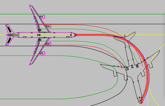
- Follow: Creates a path by tracing existing lines, arcs, and other entities in the drawing. During the construction process, a wide red transparent line highlights possible routes depending on the position of the cursor. When encountering intersections, the shortest path will automatically be selected, which may be in the wrong direction. If this is the case, click a point along the desired route before reaching the intersection, and then continue in the desired direction.
Note: If an entity or route cannot be followed, a red airplane will display at the point beyond which the path cannot be continued. Furthermore, a tooltip will display stating, “Path cannot be followed. Modify parameters in the dialog box and try again.” In this case, using your own judgment, try reducing the speed, increasing the steering limit, or applying asymmetric thrust. If the path still cannot be followed, inspect the quality of the CAD line being followed. Under circumstances, a design change or alternative operational procedure may be required (however, this is outside the responsibilities of AviPLAN Airside Pro 2024).

- FreeDrive: Creates a "freehand" path based on the selected parameters and turn type to the pointer location in the drawing. A click will finalize each path segment.
- Target: Creates a path to move along straight lines or connect to diverging lines, arcs, and other entities in the drawing. It is best to start target construction on a straight line because starting on an arc will place the aircraft/vehicle at a tangent to the arc which will not reflect the movement over the length of the arc. Typically, the Target mode is used to create turns between consecutive straight segments of line based on the selected turn type. Under circumstances during path construction, after targeting a diverging drawing element, no ghosted image of the object is shown, and the following tooltip may appear, “Current parameters prevent path construction to targeted element. Reset start point or adjust parameters and try again.” In this case, first undo and reset the previously targeted point so that it is farther away from the next, or, using your own judgment, try a different turn type, reducing the speed, adjusting the steering limit, or applying asymmetric thrust.
Note: In the Target mode, after selecting a drawing element, as the current object is shown as a ghosted image at the pointer, move the pointer along the drawing element to see the result. The targeted segment is limited to the length of the selected drawing element; to override this limit, press SHIFT and move the pointer beyond the element end.
- Parallel: Creates a path to move parallel with the lines, arcs, and other entities in the drawing. After selecting the Parallel mode, select a drawing element. This will lock the steering angle, i.e., direction of travel, to match that of the selected element. If an arc is selected, the angle will reflect a tangent at that point on the arc.
- Fixed angle: Creates a path at a locked angle in accordance with the value set in the associated value box. Hold SHIFT and then move the pointer to dynamically adjust the Turn angle value to suit the design requirements during path construction.
During path construction, it is possible to switch between the various Drive modes whenever necessary.
Turn type
Select the turn type defining the shape of the curve. When going forward the available turn types (buttons from left to right) are as follows:
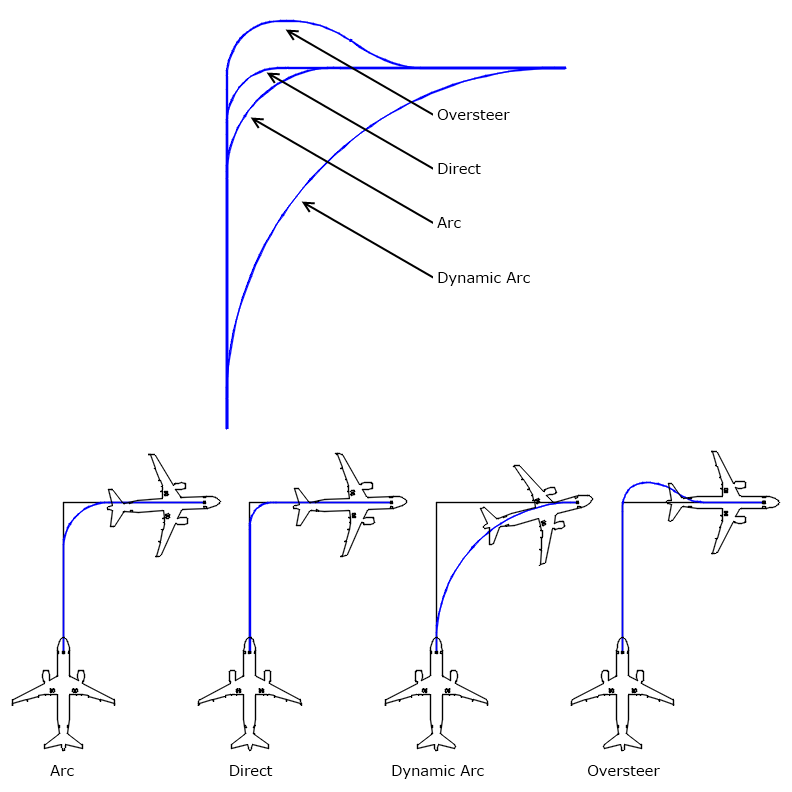
- Arc/Dynamic Arc: Arc is creating an arc element with fixed radius between start position and pointer position, complemented with a straight line if necessary to reach the cursor. This turn type is typically used for airplanes, and, therefore, it is also the default setting for this object. The alternative Dynamic Arc mode is the default setting for vehicles, and it creates an arc element where the radius is dynamically adjusted to be as large as possible, in this way creating the smoothest possible path between the starting point and the pointer position. Switch between the Arc and Dynamic Arc modes by clicking the small arrow on the right side of the button.
- Direct: A turn where the nose gear or steering wheels of the object turn as quickly as possible to the allowed steering limit. In this way, the shortest path is generated to the pointer position or to the target point/line.
- Oversteer: A turn which results in the straight alignment of the body of the object and all wheels once the turn has been completed.
When the Follow Drive mode is selected, the Turn type buttons are unavailable.
Below the turn types are visualized where the direction of movement is from bottom to right (90 degrees turn).

Turn on spot
For the Direct and Oversteer modes, an alternative is available where the wheels can be turned on the spot. This alternative can be accessed by clicking the small arrow on the right side of the button.
Note: When working with airplanes, 'turn on spot' should be used with caution. This practice may result in excessive stress on landing gears and pavement surfaces, and we therefore recommend consulting the airplane operator before applying this technique.

During path construction, it is possible to switch between the various turn types whenever necessary.
Note: For reverse movements, the above described buttons are disabled.
Construction Point
Select a construction point in the Construction Point list. This is the point that is used to construct the path. For some of the available construction points an offset can be applied. This offset can be defined in the box on the right side of the list. In case of the Drive mode "Follow," the construction point may also be called "Follow Point."
Turn Limit
Select the turn limit in the Turn limit list and the related box. This parameter defines how large the curve will be. It can never be less than the minimum turning radius of the object.
For airplanes, the turn limit is expressed as follows:
- Effective steering angle %;
- Effective steering angle (value in degrees);
- Nose gear turning radius;
- Cockpit turning radius.
For vehicles, the turn limit is expressed as follows:
- Steering angle (value in degrees);
- Steering angle %;
- Steering radius (radius for center of front axle);
- Articulated angle (when applicable);
- Articulated angle % (when applicable).
Changes can be applied per segment. Hold CTRL and then move the pointer to dynamically adjust the Turn Limit value during path construction to suit the design requirements.
Dynamic steering display
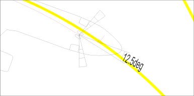
Selecting the Dynamic steering display checkbox will display a fixed element at the nose gear, depicting the maximum effective steering angle (left and right), and the current turn limit. A further “dynamic” element displays the current steering usage as the object is moved along the path.

Apply Asymmetric thrust / differential braking
Select the Apply Asymmetric thrust / differential braking checkbox to account for the effect of asymmetric thrust and differential braking resulting in an increase to the maximum effective steering angle.
Note: Asymmetric thrust / differential braking data not available for all airplanes.
More
Click the More button to access parameters that are likely to be edited relatively infrequently.
For airplanes moving forward independently using the Direct or Oversteer turn type and airplanes being pulled or pushed by a tractor, the Turn transition can be set. This is the how fast the transition into the turn is initiated by:
- The airplane pilot using his controls to turn the nose gear; or
- The driver of a pushback tractor turning the steering wheel and thereby the steering wheels of the vehicle and indirectly also the airplane nose gear
A number of pre-defined levels can be selected in the drop-down list box ranging from Very Fast to Very Slow.
Lock to Lock time
For vehicles (not connected to airplanes) and wheeled helicopters, the lock to lock time can be defined. Lock to lock time (also known as steering rate) is the time it takes to turn the steering wheel(s) from completely left to completely right or vice versa, and it has an impact on the transitional portions at the start and end of a curve. AviPLAN Airside Pro uses a default value (in seconds) that is considered realistic for the object as exact values are often not provided by the manufacturers. This value may be altered.
Follow layers
Layers/levels to be used during the process of following lines and other entities can be defined under Follow layers. The layer/level on which the object is inserted at the start of the path is automatically recognized and added to the list of layers. Two methods are available to add further layers:
- Selecting the layer/level in the list and clicking the Add Layer button.
- Clicking the Pick Layer button and selecting the layer/level from the drawing.
All layers/levels will be added to the list of layers/levels.
A layer/level can be removed from the Follow layer list by clicking it in the list and then clicking the Remove Layer button.


