GuideSIGN Plus 2024 Help
This feature is not available in GuideSIGN SIGMA.
Allows you to place a standard sign from a sign library of the M.U.T.C.D. Edition specified in Program Settings' General - Design Category dialog box.
Before placing a standard sign, make sure you specify the appropriate M.U.T.C.D. Edition and panel style for the sign (see Panel Styles' Select Current Panel Style).
Note:
Displays the panel style, drawing units, and M.U.T.C.D. Edition of the currently selected panel.
Note: The M.U.T.C.D. Edition determines the choice of standard sign templates under Browse for Standard Sign (e.g. if the current M.U.T.C.D. Edition is the 1988 one, the M.U.T.C.D. 2003 Edition standard sign templates will not display under Browse for Standard Sign). For information on how to specify the M.U.T.C.D. Edition, see Program Settings' General - Design Category.
Allows you to select a standard sign library and a standard sign.
Note: User created signs display with the  custom graphic in the browse tree.
Allows you to specify the number of standard signs displayed in the preview area below.
Displays the preview of the standard signs contained in the standard sign library that is currently open under Browse for Standard Sign.
| Button | Option | Click to... |
  |
Previous / Next | Preview the next / previous group of standard signs. |
  |
Zoom In / Zoom Out | Zoom the selected standard sign to the full viewing area. |
 |
Information | Get information on the selected standard sign. |
Before creating custom standard signs, see Preparing for Display Modes.
You are recommended to store custom standard sign libraries in appropriate folders. For information on the location of user created sign libraries, see Customizing GuideSIGN Plus -> Saving User Created Content.
Note:
Note: The actual size at which a sign is drawn is not important because it will be scaled to the correct size when it is placed, based on the panel size you selected.
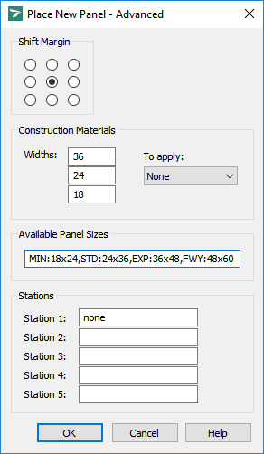
In the Place New Panel - Advanced dialog box, under Available Panel Sizes, specify a list of the available sizes for the sign. The list will consist of one or more sets of width and height dimensions.
All available sizes must be entered in one string, separated by commas.
Each size must begin with a label followed by a colon ’:’ character. After the label, enter the width and height separated by an ’x’ character. Separate Label:Size values with commas ','. No spaces are allowed.
The list of available sizes for a standard speed limit sign is shown below as an example:
MIN.:18x24,STD.:24x36,EXP.:36x48,FWY.:48x60
The table below shows the various labels and sizes for a standard speed limit sign example.
| Description | Label | Size | Label:Size |
| Minimum | MIN. | 18x24 | MIN.:18x24 |
| Standard | STD. | 24x30 | STD.:24x30 |
| Expressway | EXP. | 36x48 | EXP.:36x48 |
| Freeway | FWY. | 48x60 | FWY.:48x60 |
The size list for this example should be specified in the Place New Panel - Advanced dialog box under Available Panel Sizes as shown below:
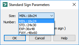
When this standard sign is placed, the list of sizes in the Standard Sign Parameters dialog box will appear as follows:
It is important that the ratio of width to height for each size is the same as the proportions of the sign stored in the library. When the sign is placed, both horizontal and vertical dimensions will be scaled to achieve the selected size. Some distortion will result if proportions are not consistent.
For example, the speed limit sign was drawn using the proportions for the standard version (24x30 or 1.25 height to width ratio). However, the published dimensions for the expressway version are 36x48, which results in a 1.33 height to width ratio. Since these proportions are not equal, this sign will be slightly stretched in the vertical direction (by about 7 percent in this case) when placed at the expressway size.
If a standard sign contains either of the strings '10', '100', or '1000', it can be replaced when the sign is placed. This is useful for placing speed limit numbers, for example.