GuideSIGN Plus 2024 Help
This feature is not available in GuideSIGN SIGMA.
If you want a custom object such as an arrow or route shield to be displayable in outline, black and white, and color, you have to create components for each of these display modes. For a general explanation of how GuideSIGN Plus uses different levels/layers to display objects in outline, black and white, and color modes, see the Program Settings - Sign Creation Features: Display - Design Category: Display Modes and Program Settings - Sign Creation Features: Display - Design Category: Printing.
The example below shows the components of a standard route shield separated so they can be seen individually. Normally, they would be drawn superimposed.
| AutoCAD/BricsCAD Layers / MicroStation Version 8 Levels | |
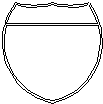 |
GSOUTLINE |
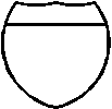 |
GSBWFILL |
 |
GSCOLORFILL |
If you do not need an object to be displayable in the three modes, multiple components do not have to be created, and the object should not be drawn on any of the display mode levels/layers because GuideSIGN Plus will always turn off two of these three levels/layers.
To get white objects to print white (in color mode), use a very light gray for objects on the color fill level/layer (level 62, or the GSCOLORFILL level/layer) instead of pure white. This is necessary because both AutoCAD/BricsCAD and MicroStation print pure white objects as black.