GuideSIGN Plus 2024 Help
This feature is not available in GuideSIGN SIGMA.
Allows you to place a drawing sheet for one or more signs, which is the first of the two steps in creating a sign drawing. The second step is placing a report (see Place Report).
Note: To create a custom drawing sheet using CAD functionality see Creating Custom Drawing Sheets in CAD.
The drawing sheets supplied with the software are intended as examples only. It is assumed that users will create their own drawing sheets either by modifying the ones supplied or by creating new ones from scratch.
Note:
 custom graphic in the list.
Specify the scale at which the drawing will be plotted. For imperial scales, you must convert the scale to a ratio (e.g. a scale of 1/4" = 1'-0" converts to a ratio of 1:48, or a Plot scale value of 48).
Specify the text height of the $origin tag of the selected drawing sheet. This value, together with the Plot scale one, will ensure that the drawing sheet is scaled to the correct size. Please note the units currently used in the software and indicated to the right of the Drawing sheet text height box. If these units do not match the units of the original drawing, you must convert the original $origin tag text height value before specifying it in the Drawing sheet text height box (e.g. if the original $origin tag text height was 2 mm, whereas the software currently uses the imperial system, the converted value specified in the Drawing sheet text height box will be 0.0787 in).
Note: The example drawing sheets supplied with the software were drawn with $origin tag text heights of 2 mm or 0.0787 in.
Select the Color check box to specify the title block text color.
Select the Font Style check box to specify the title block text font (letter series).
Select the Text Height Scale check box to specify the title block text height scale factor.
Drawing sheets usually consist of a border and title block and may include information not specifically sign related such as:
This type of information can be edited by dropping the complex status of the drawing sheet (or exploding the AutoCAD/BricsCAD block) after placing it, and then editing text strings that were incorporated into the drawing sheet to act as place holders.
For single sign layouts, the drawing sheet is placed after the sign is created. After placing the sheet, a report can be placed for the sign.
For multi-sign drawing sheets, the sheet is placed after the first sign is created. Subsequent signs are placed at snap points provided by temporary symbols in the sheet, which are later removed. Reports can then be placed for each sign.
The first of the following examples is of a single sign drawing sheet. The illustration shows the drawing sheet before the report has been placed. For an illustration of this sheet after a report is placed in it, see Place Report.
The second example shows a multi-sign drawing sheet. The illustration shows the drawing sheet before the second, third and fourth signs have been added and before any reports have been placed. For an illustration of this sheet after the rest of the signs have been created and all the reports placed, see Place Report.
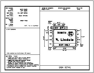
Single sign drawing sheet example
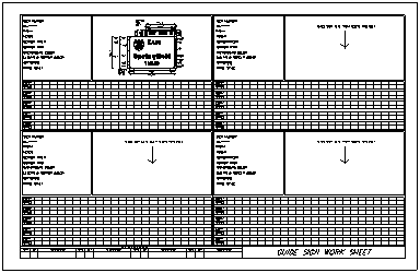
Multi-sign drawing sheet example
Since most users want to create libraries that contain only the drawing sheets they will be using, you may begin by creating a new library (see Customizing GuideSIGN Plus -> Adding Objects to Custom Libraries). You are recommended to store custom drawing sheet libraries in the Sheets folder located in the Contents User folder (see Customizing GuideSIGN Plus -> Saving User Created Content).
Each drawing sheet must contain an $origin tag. Tags are text strings beginning with a '$' character. The origin (or AutoCAD/BricsCAD insertion point) of this tag tells GuideSIGN Plus the position of the sign in the drawing sheet (i.e. the sign anchor point, which is usually the center of the panel.
The height of the $origin tag is also the representative text height used to calculate the insertion scale for the sheet. It should be the same height as other text in the drawing sheet.
The software automatically deletes the $origin tag when a drawing sheet is placed.
Add replaceable text strings such as 'PROJECT:', 'DRAWING NO.:', 'DRAWN BY:', etc. where this information will be located so the text can be edited appropriately after the sheet is placed. The complex status of the drawing sheet must first be dropped before this can be done (i.e. the AutoCAD/BricsCAD block must be exploded).
The following is an example of a single sign drawing sheet. (For an example of a report created for this drawing sheet, see Place Report: Creating Custom Reports in CAD.
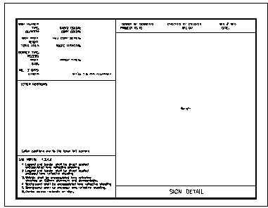
Single sign drawing sheet example
For multi-sign sheets, the $origin tag is used to locate the first sign only. This could be the upper-left sign on the sheet for example.
Subsequent signs require snap points so they can be located accurately. This insures that the data fields in reports end up in the correct locations in the sheet. Temporary symbols can be used to provide these points that can be deleted after the signs are placed. The SGNPLACE library (in SHEETS) contains a cell (or block) that can be used for this purpose.
While the above information gives an overview of the process of creating custom drawing sheets, a careful examination of the samples provided with the software is recommended to see how drawing sheets are created.
The following is an example of a multi-sign drawing sheet. Note the $origin tag which locates the first sign and the symbols (consisting of the note and arrow) indicating where the second, third, and fourth signs should be placed.
Accurate placement of the signs in this type of sheet is particularly important because it incorporates a grid of boxes where the letter locations will be placed by each report. Accurate placement of the center of each sign at the end of each symbol arrow insures that the letter table data will fit exactly inside the boxes.
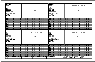
Multi-sign drawing sheet example
For an example of a report created for this drawing sheet, see Place Report: Creating Custom Reports in CAD.