GuideSIGN Plus 2024 Help
This feature is not available in GuideSIGN SIGMA.
Allows you to create a custom arrow, save it for future use, and place it in a sign panel.
Note:
Note: All options are not available for all arrow types.
To specify a name for the new custom arrow, type the desired name in the Name box.
To specify the library to which you want the software to add the custom arrow, click the desired library in the list or type a new library name.
The default type of arrow is Straight. Select the type from the available types: Straight, Down, Custom Advance Turn, Custom Advance Curved Turn, Thru, Double-headed, Curved, Thru-Turn, Split, Left-Thru-Right, and Roundabout.
Allows you to choose the units which the software should use for the custom arrow. The available units are:
If the custom arrow units do not match those of the current sign panel, the software will convert the custom arrow units as you place the arrow in the panel.
Lets you open a previously saved custom arrow to place or edit it.
To specify the desired traffic direction, click Left or Right. The arrow direction will change accordingly.
The arrow’s overall width and length are displayed. As you modify the custom arrow parameters, the Overall Width and Overall Length values will update accordingly.
Specify the number of departure legs for the roundabout arrow (maximum 8).
Displays the preview of the custom arrow. As you modify a parameter, the preview will update dynamically. To force preview the last parameter modified, press TAB. For the Roundabout arrow types, click in a numbered departure leg, base, or center to edit it's parameters.
Resets the arrow parameters to the default values. The default values are based on the M.U.T.C.D. requirements for particular arrow types.
Specify the type of fork for the roundabout arrow. The available fork types are:
 |
Arrowhead |
 |
Point |
Note: If you select the point type of fork, the only dimension available in the Fork tab under Departure Leg Details will be Length.
To specify whether the roundabout arrow should have an exit departure leg and roundabout center, select the corresponding check box(es).
Allows you to set the Width, Length, Draft, and Radius values for the custom arrow fork. The illustration below shows how the arrow fork dimensions are measured.
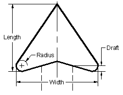
Arrow Fork Dimensions
To set the custom arrow fork parameters, type the desired values in the Width, Length, Draft, and Radius boxes.
To have the software round the tip of the fork, select the Rounded Tip check box. To round the fork tip, the software will use the value specified in the Radius box above. However, the actual forms of the fork tip and fork sides will be different because the tip angle is normally greater than the side angle.
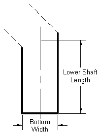
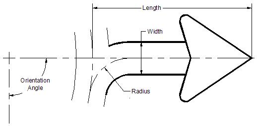
Allows you to set the dimensions for the custom straight arrow shaft. The illustration below shows how the straight arrow shaft dimensions are measured.
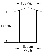
Straight Arrow Shaft Dimensions
To set the custom straight arrow shaft dimensions, type the desired values in the Length, Top Width, and Bottom Width boxes.
Allows you to set the dimensions for the custom thru-turn and left-thru-right arrows' straight shaft. The illustration below shows how the thru-turn arrow straight shaft's dimensions are measured.
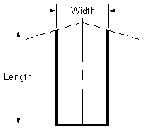
Thru-Turn and Left-Thru-Turn Arrow Straight Shaft Dimensions
To set the thru-turn and left-thru-right arrow straight shaft dimensions, type the desired values in the Length and Width boxes.
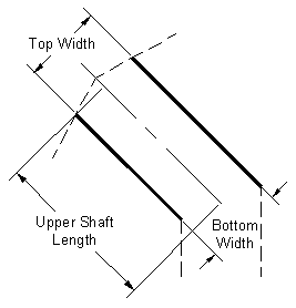
Allows you to set the dimensions for the custom thru-turn and left-thru-right arrows' curved shafts. The illustration below shows how the curved shaft's dimensions are measured.
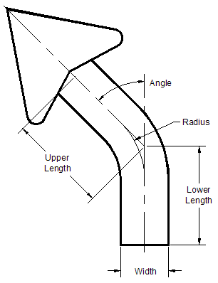
Thru-Turn and Left-Thru-Right Arrow Curved Shaft Dimensions
The curved shaft radius is measured from the center to the middle of the shaft width.
To set the thru-turn arrow curved shaft dimensions, type the desired values in the Upper Length, Lower Length, Width, Angle, and Radius boxes.
Note:
Allows you to set the dimensions for the custom double-headed arrow's shaft. The illustration below shows how the double-headed arrow shaft's length and width are measured.
Double-headed Arrow Shaft Length and Width
The angle is measured from 0 degrees East.
To set the custom double-headed arrow shaft dimensions, type the desired values in the Length, Width, and Angle boxes.
Note: By default, the Length and Width values specified for Shaft 1 are automatically applied to the corresponding dimensions of Shaft 2. If you want to specify a different value for either of these dimensions for Shaft 2, clear the respective check box(es) under Uniformity Locks.
Allows you to set the dimensions for the custom split arrow's shaft. The illustration below shows how the split arrow shaft's dimensions are measured.
Split Arrow Shaft Dimensions
The shaft radius is measured from the center to the middle of the shaft width.
To set the split arrow shaft dimensions, type the desired values in the Upper Length, Lower Length, Width, Angle, and Radius boxes.
Note:
Allows you to set the dimensions for the custom advance turn arrow upper shaft. The illustration below shows how the turn arrow upper shaft's length, top width, and bottom width are measured.
Custom Advance Turn Arrow Upper Shaft Length, Top Width and Bottom Width
The illustration below shows how the upper shaft bend angle is measured.
Custom Advance Turn Arrow Upper Shaft Bend Angle
To set the custom advance turn arrow upper shaft dimensions, type the desired values in the Length, Top Width, Bottom Width, and Angle boxes.
Note: The top width of the shaft affects both the bottom widths of the shaft and the radius of the fork.
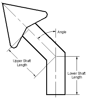
Allows you to set the dimensions for the custom advance turn arrow lower shaft. The illustration below shows how the custom advance turn arrow lower shaft dimensions are measured.
Custom Advance Turn Arrow Lower Shaft Dimensions
To set the custom advance turn arrow lower shaft parameters, type the desired values in the Length and Bottom Width boxes.
To have the software make the shaft of the custom advance turn arrow filleted, select the Filleted Shaft check box, and then modify the Bend Radius value as desired.
To specify the bend radius for the custom advance turn arrow filleted shaft, type the desired value in the Bend Radius box.
Note: The Bend Radius check box is only available if you are creating a custom advance turn arrow with a filleted shaft.
Allows you to set the dimensions for the custom advance curved turn arrow's shaft. To have the software curve the shaft of the turn arrow, select the Curved Shaft check box. The illustration below shows how the custom advance curved turn arrow shaft's radius, top width, and bottom width are measured.
Custom Advance Curved Turn Arrow Shaft Radius, Top Width and Bottom Width
The shaft radius is measured from the center to the middle of the shaft width.
The following illustration shows how the custom advance curved turn arrow's sweep angle is measured.
Custom Advance Curved Turn Arrow Sweep Angle
To set the custom advance curved turn arrow shaft dimensions, type the desired values in the Radius, Top Width, Bottom Width, and Angle boxes.
Note:
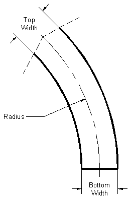
Allows you to set the dimensions for the curved arrow's shaft. The illustration below shows how the curved arrow's shaft dimensions are measured.
Curved Arrow Shaft Dimensions
The shaft radius is measured from the center to the middle of the shaft width.
To set the curved arrow shaft dimensions, type the desired values in the Upper Length, Lower Length, Width, Angle, and Radius boxes.
Note: Modifying the Radius value changes the length of the shaft and, respectively, the overall length of the arrow, so make sure the Overall Length value displayed under Current Arrow Data remains within the desired limits.
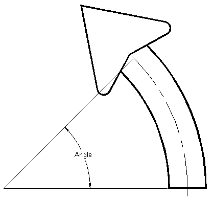
Allows you to set the dimensions for the custom roundabout (perpendicular) arrow's shaft. The illustration below shows how the roundabout (perpendicular) arrow shaft's dimensions are measured.
Roundabout (Perpendicular) Arrow Shaft Dimensions
To set the roundabout (perpendicular) arrow shaft dimensions, type the desired values in the Length, Width, Radius, and Orientation Angle boxes.
Note:
Allows you to set the dimensions for the custom roundabout (rotated) arrow's shaft. The illustration below shows how the roundabout (rotated) arrow shaft's dimensions are measured.
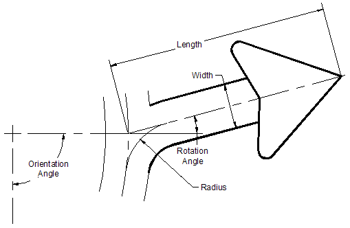
Roundabout (Rotated) Arrow Shaft Dimensions
To set the roundabout (rotated) arrow shaft dimensions, type the desired values in the Length, Width, Radius, Orientation Angle, and Rotation Angle boxes.
Note:
Allows you to set the dimensions for the custom roundabout (radiused) arrow's shaft. The illustration below shows how the roundabout (radiused) arrow shaft's dimensions are measured.
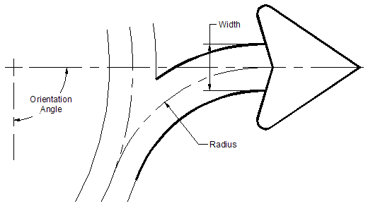
Roundabout (Radiused) Arrow Shaft Dimensions
To set the roundabout (radiused) arrow shaft dimensions, type the desired values in the Width, Radius, and Orientation Angle boxes.
Note:
Allows you to set the dimensions for the roundabout arrow base. The illustration below shows how the roundabout arrow base dimensions are measured.
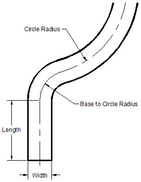
Roundabout Arrow Base Dimensions
To set the roundabout arrow base dimensions, type the desired values in the Length, Width, Circle Radius, and Orientation Angle boxes.
Note: The Width value of the base must be greater than or equal to the Width value of the shaft.
Specify the radius for the center of the roundabout.
Select the check boxes to have the relevant Fork 1 and Shaft 1 dimensions applied to the other forks and shafts respectively. Clear the check boxes to specify different values for the corresponding fork and shaft dimensions.
Allows you to add the description for the current custom arrow.
|
|
Straight Arrow |
An arrow with a straight shaft. |
|
|
Down Arrow |
A down arrow has a much larger fork in relation to its shaft and is treated differently than other arrows in that sign panel bottom margins can be reduced for down arrows. |
|
|
Custom Advance Turn Arrow |
A custom advance turn arrow with a two-part shaft: the lower straight vertical shaft and the upper shaft bent at a user specified angle. Types: 45 Degree Advance Turn, 90 Degree Advance Turn, and Custom Advance Turn. |
|
|
Custom Advance Curved Turn Arrow |
A custom advance turn arrow with a shaft curved at a user specified sweep angle. |
|
|
Thru Arrow |
A diagrammatic arrow with a straight shaft where the shaft length is significantly longer than the straight arrow proportions and where the shaft cannot be tapered. |
|
|
Double-headed Arrow |
A diagrammatic arrow with two heads providing directional guidance where no base shaft is included to keep the arrow size compact for smaller signing applications. |
|
|
Curved Arrow |
A diagrammatic arrow with linear upper and lower shafts joined by a middle radial shaft. |
|
Thru-Turn Arrow |
A diagrammatic arrow with two heads providing directional guidance, where one arrow head is a linear continuation of the base shaft, and the second arrow head is a radial departure from the base shaft. | |
|
Split Arrow |
A diagrammatic arrow with two heads providing directional guidance, where both arrow heads are radial departures from the common linear base shaft. | |
|
Left-Thru-Right Arrow |
A diagrammatic arrow with three heads providing directional guidance, where the middle arrow head is a linear continuation of the base shaft flanked on either side by arrow heads that are radial departures from the common linear base shaft. | |
|
Roundabout Arrow |
A multi-headed diagrammatic arrow to be graphically representative of the number of legs (roadways departing the roundabout) as well as the departure angle for each of the legs in relation to the base shaft representing the approaching roadway. |
A custom arrow created with the Create Custom Arrow tool is saved to a GuideSIGN Custom Arrow (.gca) file. The software stores .gca files in the user specified Library folders located in the ..\Contents User\Arrows folder (see Customizing GuideSIGN Plus -> Saving User Created Content).
Note: An arrow created with the Create Custom Arrow tool cannot be resized as it is placed in a sign panel (i.e. the Fork width and Length boxes will remain unavailable if you select the Manual override check box in the Arrow Parameters dialog box - see To Place a Custom Arrow). If you want to create a resizable custom arrow, you have to use the CAD (AutoCAD/BricsCAD/MicroStation) functionality for it (see Creating Custom Arrows in CAD).
Before creating custom arrows, see Customizing -> Preparing for Display Modes.
You are recommended to store custom arrow libraries in the Arrows folder located in the Contents User folder (see Customizing GuideSIGN Plus -> Saving User Created Content).
Arrows must be drawn with the width across the forks equal to 500 drawing units (i.e. mm). This is required because GuideSIGN Plus uses the fork width as the basis for sizing arrows. With the fork width set to a particular value, GuideSIGN Plus will be able to determine how to scale the arrow for placement.
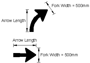
Arrow Dimensions
GuideSIGN Plus has the ability to stretch arrows to any length in the longest dimension, either down, or to the left. For this reason, if you wish to be able to stretch an arrow, draw it pointing either up or to the right so that the end of the shaft is at the bottom or the left side of the arrow.
Arrows that may be rotated should be drawn pointing to the right.