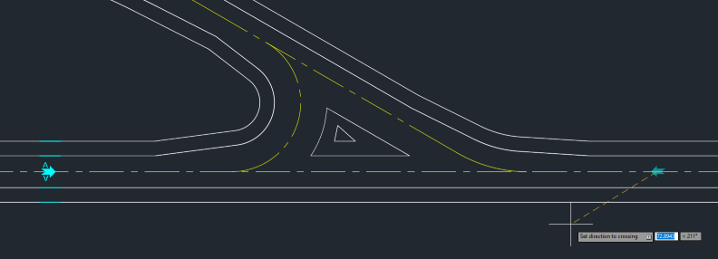

In the Entries tab the characteristics of the taxiway intersection are defined.
To set the position of an entry, left-click on the applicable drawing line element designating the taxiway centerline. Once the position is confirmed, move the cursor in the appropriate direction to set the direction of the entry so that the arrow symbol is pointing towards the intersection. Click again to confirm and the entry will be added to the table in the Entry tab. Repeat this process to add additional entries. Each Entry can be removed with a Remove button or Moved to another position with the Move button.

This is a text label visible in the drawing, results and reports.
It is critical that the dimensions of the straight portion of the taxiway and shoulders that connect to the taxiway intersection under consideration are set for each Entry.
ICAO/EASA
The ICAO/EASA OMGWS (Outer Main Gear Wheel Span) drop-down list changes the width of straight portion of the taxiway (displayed in the Taxiway column) and the ICAO/EASA Code drop-down list changes the width of total taxiway width, including shoulders (displayed in the Taxiway & Shoulders columns). Dimensions are set in accordance with:
ICAO - ICAO Annex 14 Volume 1 Eighth Edition Amendment 16 (July 2018, amended September 2020) paragraphs 3.9.4 and 3.10.1;
EASA - EASA CS-ADR-DSN Issue 6 (March 2022) paragraphs CS ADR-DSN.D.245 and CS ADR-DSN.D.305.
FAA
The FAA TDG drop-down list changes the width of straight portion of the taxiway (displayed in the Taxiway column) and the total taxiway width, including shoulders (displayed in the Taxiway & Shoulders column). Dimensions are set in accordance with:
FAA - FAA AC 150/5300-13B (March 2022) paragraph 4.2 and table 4-2.
For all regulations, user-defined dimensions can be entered directly into the applicable cell in the Taxiway column to override the regulatory default dimensions.
As soon as at least one Route has been established and one entry criteria-compliant airplane has been added¹, the Calculate button ![]() will be enabled. After clicking Calculate, the tool will analyze the critical airplanes' movements through the intersection using the cockpit over centerline method, as demanded by ICAO, EASA and FAA. Once the calculation process is finalized, the calculated fillet and shoulder lines are displayed in the intersection and the Fillet Results dialog will be updated. The calculated fillet and shoulder lines, together with a range of other elements, can be controlled using the Session Manager.
will be enabled. After clicking Calculate, the tool will analyze the critical airplanes' movements through the intersection using the cockpit over centerline method, as demanded by ICAO, EASA and FAA. Once the calculation process is finalized, the calculated fillet and shoulder lines are displayed in the intersection and the Fillet Results dialog will be updated. The calculated fillet and shoulder lines, together with a range of other elements, can be controlled using the Session Manager.
Note¹: [FAA only] The airplanes selected in the Airplanes tab do not contribute to Taxiway, calculated edge or Shoulder, calculated edge. See Fillet Results for more information. Accordingly, airplanes do not need to be added to the Airplanes for the Calculate button to be enabled.
Press the More... button to access parameters that are likely to be edited relatively infrequently.
It is possible to place entries on multiple CAD layers / levels. It is recommended that all layers that are to be used in the session are added to the available layers list prior to placing any entries, however this setting my also be altered after an entry(ies) has been placed. If a route is not detected once two or more entries have been placed, review the Centerline layer setting to verify that the settings are correct and, if any layers are added, the tool will recalculate to determine if any new routes are available.Two methods are available to add further layers:
All layers/levels will be added to the list of layers/levels shown in the box below.
A layer/level can be removed as Follow layer by clicking it in the selection box and pressing the Remove Layer button.