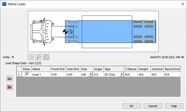

Allows you to define load shapes for any part of the current vehicle.
Note: If Permissions are enabled, you must have the Standard or higher access level to add, draw, or delete loads (see Program Settings -> Permissions Category: Access Levels).

Example of a load applied to a vehicle's second part
Displays the applied load(s) in the vehicle. The load datum located at the front-center point of the load is represented by the graphic.

In the case of multi-part vehicles, the entire vehicle or each vehicle part can be displayed by clicking  /
/  (Zoom In / Zoom Out) respectively. Each vehicle part can be navigated to by clicking
  /
/  (Next Part / Previous Part).
Displays a list of loads added to the current vehicle part and their parameters.

Adds a load shape to the current part of the vehicle.
Hint: Navigate to the desired part before clicking Import Load.
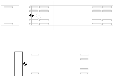
Importing a load shape requires existing CAD geometry in the drawing to represent the load. The geometry needs to be a polyline in AutoCAD or a complex chain, shape, or complex shape in MicroStation. The load needs to be drawn in relation to the vehicle part (pointing left) that the load is to be associated with. The load datum (reference point) is the same as the part datum by default (the front, center of the vehicle part) when importing the load.

Example of loads and datum points

Removes the selected load.
Allows the load associated with the current vehicle part to be drawn when generating simulations, running animations, placing vehicles in a simulation, or updating simulations.
Specify the name of the load.
Specify the distance back from the part datum (front, center of the vehicle part) to the load datum.
Specify the distance from the part datum (front, center of the vehicle part) to the load datum in the direction of the Side value.
Select either Right or Left in the list to specify the side of the vehicle that the Side Distance is applied to.
Specify the rotation angle of the load measured counter-clockwise from the load datum parallel to the centerline of the vehicle part.
Select 2D Only, 2D & 3D, or 3D Only in the list to specify the load type.
Note: The following settings are only available for the 2D & 3D and 3D Only load types.
Specify the distance from the ground to the lowermost point of the load.
Specify the height of the load, assuming the load is flat.
Specify the distance from the Z Datum height to the bottom of the raised end of the load. This setting is for a load that is not lying flat on the trailer.
Select either Right or Left to specify which end of the load is raised.