
To make it possible to display a side view or profile picture of each vehicle in the vehicles dialog boxes, profile drawings must be available to AutoTURN Pro. Profile drawings are included with the software for all the supplied vehicles.
However, if you create a custom vehicle and wish to be able to do any of the following, then a profile drawing must be created:
Creating a profile drawing is optional because AutoTURN Pro will automatically display a plan view if no profile drawing exists. However, the Insert Profile tool requires a profile drawing.
Drawings should be created with the following layer/level setup:
| Layer/Level | Description |
| ATVEHICLE | All lines pertaining to the vehicle |
| ATDIMS | All dimension lines |
| ATTEXT | All dimension labels and text |
| ATCONNECTION | Front and rear connector circles to link part profiles |
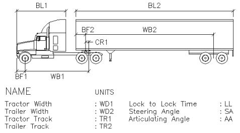
Profile drawings must contain text elements called tags that tell AutoTURN Pro where particular vehicle dimensions or other parameters are to be placed. The tags are text strings of 2 or 3 characters that represent the various possible dimensions that can be applied to each vehicle part, and some that apply to the vehicle as a whole.
Note: A tag must be created as a single line object (e.g., using the TEXT or DTEXT command in AutoCAD).
For each vehicle part, use the following tags followed by a number indicating the part number:
| Tag | Description |
| BF | Body Front Overhang |
| WB | Wheelbase |
| BL | Body Length |
| BP | Body Front to Pivot |
| CR | Rear Axle Group Center to Connector |
| WD | Width |
| TD | Maximum Telescoping Distance |
| CO | Cargo Front Overhang |
| RO | Cargo Rear Overhang |
| CL | Cargo Length |
| CW | Cargo Width |
| EW | Cargo Effective Wheelbase |
| CA | Cargo Articulating Angle |
| TR | Front Track |
| RT | Rear Track |
| LIB | Library Name |
| AA | Maximum Articulating Angle |
| MT | Minimum Centerline Turning Radius |
Note: The cargo’s front overhang is measured from the bunk on the preceding part.
For the whole vehicle:
| Tag | Description |
| LL | Lock to Lock Time |
| SA | Steering Lock Angle |
Each part's tag includes a number corresponding to its part number.

Example of a typical vehicle profile drawing for a vehicle with two parts
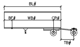
For trailer part profiles, use the "#" symbol after the tag for sequencing when you want to use the part multiple times in the same vehicle - AutoTURN Pro will replace the "#" symbol with the corresponding part number when the vehicle is displayed or drawn.

Example of a part profile drawing for a trailer