GuideSIGN Plus 2024 Help
l This feature is not available in GuideSIGN.
Allows a reference line to be added.
Note: This tool requires existing CAD elements in the drawing to act as the reference lines. The elements may consist of lines and arcs, a polyline/complex chain, or an alignment. Lines and arcs can not be combined with polylines/complex chains or alignments.
Note: This procedure assumes that the Reference Line Manager dialog box is open (see Tools -> Reference Line Manager):
![]()
Reference Line Manager
Click ![]() Add Reference Line, then pick the desired elements in the stationing direction, and then click a blank area in the drawing. The following dialog box displays (for detailed information on the dialog box, see Tools -> Reference Line Manager -> Reference Line):
Add Reference Line, then pick the desired elements in the stationing direction, and then click a blank area in the drawing. The following dialog box displays (for detailed information on the dialog box, see Tools -> Reference Line Manager -> Reference Line):
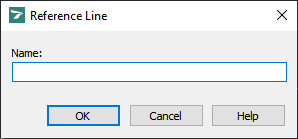
Reference Line
Note: The starting point and direction of the reference line will be based on the first object or polyline section selected. The starting point is considered the datum (point 0). Sign support symbols will be placed in reference to the datum by the actual distance along the reference line, perpendicularly projected out by the horizontal clearance distance.
In the Name box, type a unique name for the reference line. Click OK. The following dialog box displays (for detailed information on the dialog box, see Tools -> Reference Line Manager -> Sign Assembly Placement Method):
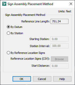
Sign Assembly Placement Method
Select By Datum, By Station, or By Reference Location Signs and then specify the Starting Station and Station Interval if By Station was chosen, or specify the reference location sign file by clicking Browse if By Reference Location Signs was chosen.
Click OK. The following dialog box displays (for detailed information on the dialog box, see Tools -> Reference Line Manager -> Horizontal Clearance):
![]()
Horizontal Clearance
In the Horizontal Clearance box, specify the horizontal clearance for the reference line.
Click OK. The following dialog box displays:
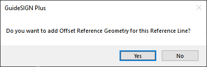
To add offset reference geometry to the reference line, click Yes, then pick the desired elements in the stationing direction, and then click a blank area in the drawing.
To return to the Reference Line Manager dialog box without adding offset reference geometry to the reference line, click No.
Note: You can add offset reference geometry to the reference line later by using the Reference Line Manager tool (see Adding Offset Reference Geometry).
If you added offset reference geometry at step 5, the following dialog box displays (for detailed information on the dialog box, see Tools -> Reference Line Manager -> Offset Reference Geometry):
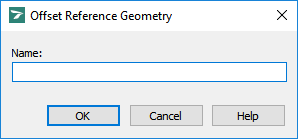
Offset Reference Geometry
In the Name box, type a unique name for the offset reference geometry.
Click OK. The following dialog box displays (for detailed information on the dialog box, see Tools -> Reference Line Manager -> Horizontal Clearance):
![]()
Horizontal Clearance
In the Horizontal Clearance box, specify the horizontal clearance for the offset reference geometry.
Click OK to return to the Reference Line Manager dialog box.
Note: An element added as a reference line or offset reference geometry can be modified (i.e. stretched, filleted, scaled, etc.) but if it is deleted, its replacement will not be included in the reference line or offset reference geometry. Deleting such an element will also result in all corresponding sign assemblies being treated by GuideSIGN Plus as if they have been freely placed for assembly editing or reporting. If the deleted element is recreated and defined as a reference line with the original name, the corresponding sign assemblies will automatically inherit the positional placement (distance/station) relative to the reference line.