GuideSIGN Plus 2025 Help
This feature is not available in GuideSIGN SIGMA.
Places dimensions on a sign panel or standard sign using the current AutoCAD/BricsCAD or MicroStation text style.
Overall dimensions can also be placed for any object that is not contained within a panel (such as an arrow or shield moved or copied outside a sign) by clicking the object.
Click this button to change the dimensions parameters that were set in Program Settings' Dimensions - Design Category.
GuideSIGN Plus controls the height of the text for creating dimensions using the values indicated in the Plot Scale and Plotted Text Height boxes. Set the Plot Scale value to the scale the drawing will be plotted at, and then set the Plotted Text Height value to the actual height you want the dimension text to be when it is plotted at the plot scale.
The Color list makes it possible to select the color for all dimension elements including text, lines, and arrow heads.
The Style list makes it possible to specify whether the dimensions are drawn with arrows or ticks, and whether the dimension lines are broken or continuous.
To have the letter position dimensions drawn in the sign when dimensions are placed or updated, click the desired style in the Letter positions list, and then select the Letter positions checkbox below. The Letter positions styles are described in the table below.
| Coords / Panel | X coordinates of each letter measured from the edge of the sign. |
| Coords / String | X coordinates of each letter measured from the start of the text string Text components combined into one object recognized by the software. Text strings are created by using Text Styles in the Place Highway Text tool or by creating them in the Highway Text - Advanced dialog box. |
| Spaces Between | Horizontal distances from the start of one letter to the start of the next one. |
| Word Lengths | Lengths of words. |
| Letter Widths | Widths of letters. |
Determines how the sign dimensions will be displayed in the drawing. The options are Program units, Master units, Sub units, and Master-Sub units. The latter three settings always use two decimal places of precision. The Program units setting will use 1 foot = 12 inches or 1m = 1000 mm depending on the Units setting in the Panel Styles dialog box (i.e., either inches or millimeters respectively).
This setting also determines the units used in the Place Report and Place Object Dimensions tools.
The Text style list makes it possible to select the text properties (i.e., font and font style) for displaying dimension text.
Determines the way inch dimensions are displayed in dimensions and reports. The fractions display options are described in the table below.
| Eighths - fractions | The fractional portion of the dimension text is rounded to the nearest eighth of an inch and displayed as a fraction (e.g., 1/8, 1/4, 3/8, 1/2, 5/8, 3/4, 7/8) |
| Eighths - 3 decimals | The fractional portion of the dimension text is rounded to the nearest eighth of an inch and displayed with three decimal places (e.g., 0.125, 0.250, 0.375, 0.500, 0.625, 0.750, 0.875) |
| Tenths - 1 decimal | The fractional portion of the dimension text is rounded to the nearest tenth of an inch and displayed with one decimal place. |
| Hundredths - 2 decimals | The fractional portion of the dimension text is rounded to the nearest hundredth of an inch and displayed with two decimal places. |
| Thousandths - 3 decimals | The fractional portion of the dimension text is rounded to the nearest thousandth of an inch and displayed with three decimal places. |
Dimensions are normally placed around all four sides of a sign panel. However, in some cases (e.g., if two sign panels are set together) the Dimension Sides checkboxes may be selected or cleared so the dimension sides will not overlap an adjacent panel when placed.
The Dimension Sides checkboxes are normally selected automatically. The Dimension Sides checkboxes should normally be all selected. Clearing any of the checkboxes allows dimensions to be manually shut off on the corresponding side(s).
Clearing any of the Dimension Sides checkboxes also prevents adjacent panels from being dimensioned automatically. This can be useful for placing border specs on only certain panels in an arrangement where several panels are touching.
To have the various dimension options displayed in the drawing, select the desired checkboxes in this area. The dimension display options are described in the table below.
| Text above dimension line | Places the text of all the width and height dimensions above the dimension lines. |
| Multiple horizontal dimension lines | Adds dimension lines for each horizontal line of content (text, arrows, shields, etc.) in the panel. |
| Horizontal extension line breaks | Draws a gap in the horizontal extension lines between successive vertical dimension lines. |
| Letter positions | Displays letter positions above each letter in the sign, measured from the left side of the panel. |
| Symbol names | Displays symbol names below each symbol’s height dimension. |
| Widths | Displays the width of each text string and symbol below the height dimension. |
| X coordinates | Displays the X coordinate of the lower left corner of each text string and symbol. |
| Border specs | Displays the sign border radius (R), thickness (TH) and distance inset from the panel edge (IN). |
| Panel style | Displays the name and M.U.T.C.D. Edition from which the panel was created. |
| Aligned text | Rotates the vertical dimension text to be aligned with the dimension line. |
| Show font | Displays the font letter series next to the dimension for a line of text. |
| Overall Dim (inch) | Displays the overall width and height of the sign panel in inches. When this checkbox is cleared, the overall dimensions are displayed in feet and inches. This option is ignored when the units are set to mm (see Program Settings' General - Design). |
Select this checkbox to save the current dimensions settings as the Program Settings defaults.
The first of the following examples shows typical sign dimensions. The second example shows objects dimensioned outside a sign panel.
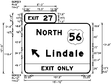
Place Dimensions example (panel)
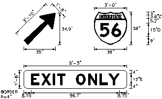
Place Dimensions example (objects)