GuideSIGN Markings 2024.8.2
The user is given a large number of different commands due to the number of linetypes defined in the MUTCD. It is expected the user will have the expertise of a traffic engineer to know which type of marking is required in which location. This information is obtained from the descriptions and directions in the MUTCD.
As might be expected with all the different uses and types of line, the input of these points is tailored to provide the most useful easy method for each particular type.
There are a number of icons that select the required linetype and also line width.
| Description | Comment | |
|---|---|---|
|
or
|
||
| Signal stop line |
12” for USA 300mm for AU/NZ |
|
| Yield Triangles | Draw like a line, but is a series of blocks | |
| Holding line | 0.6m line + 0.6m gap | |
| Roundabout circulatory | Dashed line | |
| Give way |
To draw:
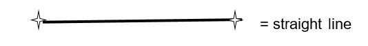
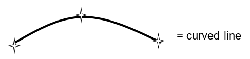
Short lines can be drawn as either a straight line or an arc. The 2 points = straight line & 3 points = arc principle is one that is used frequently throughout the GuideSIGN Markings commands.
Line (2 points):
AutoCAD: Select 1st point, select 2nd point, press Enter to finish.
– results in a straight line through the two selected points.
Microstation: Select 1st point, select 2nd point, right-click to finish.
– results in a straight line through the two selected points.
Arc (3 points):
AutoCAD: Select 1st point, select 2nd point, select 3rd point
– results in an arc being drawn through the three selected points.
Microstation: Select 1st point, select 2nd point, select 3rd point
– results in an arc being drawn through the three selected points.
Each of the points chosen can be subject to the optional split function detailed in section Split Function.
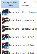
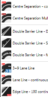
There are quite a few lines that are drawn in this way. They all use the same identical method to draw them and GuideSIGN Markings changes the layer, linetype and color as necessary. The user will select the appropriate icon for the linetype (and width), such as these below.
| Description | Comment | |
|---|---|---|
|
or |
Centre line | Metric or imperial depending on the territory initialized |
| Lane line | ||
| Edge line | ||
| Hazard line | ||
| Bus lane | Widths and line types | |
| Cycle lane | As per MUTCD | |
| Dashed lane | ||
| Dotted line | ||
| Yellow line | Color as per MUTCD | |
| White line |
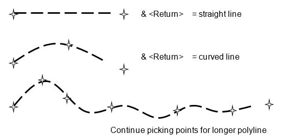
These all start off being drawn in a similar way as in Short Lines, i.e., the 2 points = straight line & 3 points = arc principle, but if you don’t press Enter or right-click, then you can continue drawing as a polyline using many arc or line segments until you press to finish the line or marking.
However, for linetypes consisting of a line plus gap linetype, the situation is more interesting. Experienced users of CAD systems will appreciate that CAD normally insists that each section of line must start and end with a length of line rather than a gap. Accordingly, the first and last parts of any dashed CAD line will be longer or shorter than the requested linetype, to be able to fit into the selected endpoints. When drawing road markings, it is desirable to show all the line markings to the correct length in order that the road marking drawing and required stripe length is fully understood.
GuideSIGN Markings overcomes these CAD restrictions, and line plus gap linetypes chosen from menus are always drawn in exact module lengths.
Note
For dashed linetype it may not reach the final selected point. GuideSIGN Markings draws the dashes along a hidden base line and appears to finish with a gap.
Note
For Microstation, using right-click is used rather than pressing Enter in the above image.
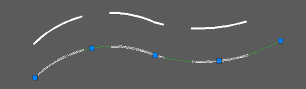
You will notice that a feature of GuideSIGN Markings is that the original drawn line is still remembered after you have drawn the dashed line. If you select and highlight the dashed marking, a green base line appears and the blue AutoCAD grips are shown at the end of this line not the white road marking. This means you can stretch, extend or alter the marking and the correct length lines (e.g., 4 ft line plus 2 ft gap) will always be maintained.