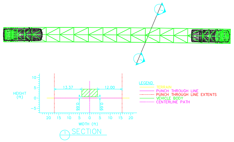

Draws a cross section of a selected 3D turn simulation at a cutting plane line and creates an annotated section detail.
Note: The cutting line must be a line element - not a polyline.

Analyze Punch Through example
Set the layer/level that the punch through section will be drawn on in the following ways:
Specify the section name (maximum 3 characters) that is drawn in the section detail symbols.
Specify a sizing factor to be applied to the section detail.
Select this checkbox to draw a diagonal hatch pattern in the vehicle body punch through. The Vehicle Body color is used as the hatch color.
Select this checkbox to draw a diagonal hatch pattern in the vehicle load punch through. The Vehicle Load color is used as the hatch color.
Select this checkbox to have the legend drawn in the section detail.
Select this checkbox, and then specify the Top Offset and Side Offsets values for the 3D body clearance envelope.
Select this checkbox, and then specify the Top Offset and Side Offsets values for the 3D vehicle load clearance envelope.
Select this checkbox to generate multiple cross sections. Cross sections will be cut at the Interval value from the picked section line, in the Direction selected, to the Distance value specified or to the start/end of the simulation.
Select the direction that the cross sections should be cut relative to the direction of travel: Forward - from the selected section line towards the end of the simulation; Backward - from the selected section line towards the start of the simulation; or Both.
Type or select the desired value for the distance between cross sections.
Select Distance and type a value. Sections will be cut at the Interval value to this distance.
Select Simulation to have sections cut at the Interval value to the start/end of the simulation.
Note: If Both is selected in the Direction list, a cross section will be cut at the selected section line and then in both directions at the Interval value until one half of the Distance value or start/end of the simulation is reached in each direction where a final cross section will be cut.
Select this checkbox to draw the line representing the overall punch through and set the color and style for the line.
Select this checkbox to draw the line representing the terrain and set the color and style for the line.
Select this checkbox to draw the line representing the punch through line and set the color and style for the line.
Select this checkbox to draw the outline of the punch through and hatching when selected and set the color and style for the outline.
Set the color and line style for the outline of the body clearance. This option is made available when the Draw Body Clearance checkbox is selected.
Select this checkbox to draw the outline of the vehicle load and hatching when selected and set the color and style for the outline.
Set the color and line style for the outline of the vehicle load clearance. This option is made available when the Draw Load Clearance checkbox is selected.
Select this checkbox to draw the line representing the center of the vehicle path and set the color for the line.
Select this checkbox to draw the vertical lines at the ends of the punch through line and set the color and style for the lines.
Select this checkbox to draw the dimensions and set their color.
Select this checkbox to draw the horizontal and vertical axis, legend, and section symbols and set their color.