Allows offset reference geometry to be added to a reference line (see Managing Reference Lines).
Note: This tool requires existing CAD elements in the drawing to act as the offset reference geometry. The elements may consist of lines and arcs, a polyline/complex chain, or an alignment. Lines and arcs can not be combined with polylines/complex chains or alignments.
To Add Offset Reference Geometry:
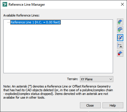
Note: This procedure assumes that the Reference Line Manager dialog box is open (see Tools -> Reference Line Manager):
Reference Line Manager
-
Under Available Reference Lines, select the reference line to which you want to add offset reference geometry.
-
Click
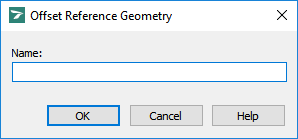
 Add Offset Reference Geometry, then pick the desired elements in the stationing direction, and then click a blank area in the drawing. The following dialog box displays (for detailed information on the dialog box, see Tools -> Reference Line Manager -> Offset Reference Geometry):
Offset Reference Geometry
-
In the Name box, type a unique name for the offset reference geometry.
-
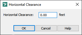
Click OK. The following dialog box displays (for detailed information on the dialog box, see Tools -> Reference Line Manager -> Horizontal Clearance):
Horizontal Clearance
-
In the Horizontal Clearance box, specify the horizontal clearance for the offset reference geometry.
-
Click OK to return to the Reference Line Manager dialog box.
-
(Optional) To add another offset reference geometry element to the same reference line, repeat steps 2 through 6.
Note: An element added as a reference line or offset reference geometry can be modified (i.e. stretched, filleted, scaled, etc.) but if it is deleted, its replacement will not be included in the reference line or offset reference geometry.


