AQCESSRAMP 1.1 Help
Generate Ramp
This tool generates curb ramps by picking curb geometry in the drawing.
This tool requires existing geometry in the drawing:
An alignment is a vertical CAD platform specific geometric arrangement of a roadway (e.g. tangents and curvatures). Alignments are assumed to have profiles created for them.
If you have problems using this tool, try these steps:
Select the desired jurisdiction design guideline from the list.
Select the desired ramp type from the list.
Select this check box to generate two ramps of the same type that are placed next to each other (e.g. at two crosswalks on a corner).
Displays a preview of the selected ramp type.
The curb standard defaults to the value set in the design guideline for this ramp type. Select the desired curb standard for the curb ramp to be drawn.
The curb type defaults to the value set in the design guideline for this ramp type. Select the type of curb drawn at the street from the list.
Specify the anchor point location on the curb from the list.
Select the vertical profile associated with the alignment that was just picked in the drawing.
OR
Choose Extract From Geometry if the selected polyline has a non-zero z coordinate.
OR
Choose Fixed Elevation to specify a fixed elevation for the selected line, arc, or polyline / complex chain.
Note: Specify relevant elevations if you are working with a combination of alignments and polylines / complex chains or lines/arcs for the primary and secondary geometry.
Specify the line segment interval for curves in the selected geometry.
Specify a fixed elevation for the selected geometry.
Select Pick secondary geometry and then pick the secondary geometry in the drawing.
OR
Select Offset primary geometry, specify an Offset Distance value and then pick the direction of the offset in the drawing.
Select the surface that is used to determine the elevations of the sawcut lines and then pick a point in the drawing to place the ramp.
This dialog box, combined with grip editing, allows the curb ramp to be designed to conform to the specified guidelines.
Adjust lengths and widths via the dialog box or grip editing.
Adjust elevations via the dialog box.
Most of the Calculated Values of the curb ramp are governed by Design Conditions which were specified in the creation of the Design Guideline. Values that appear in red fall outside of the range set in the Design Condition.
There are many ramp types available in the software and each one may not have all of these sections or aspects represented. Below is a list of all sections that may be encountered.
The ramp length for perpendicular curb ramps is measured from the landing down to the face of curb or flow line depending on the type of curb. For the parallel curb ramps, it is measured from the conform line down to the landing.
The ramp width for perpendicular curb ramps is measured between the flares or retaining curbs. The ramp width and landing width are the same value for perpendicular curb ramps. For parallel curb ramps the ramp width is the narrowest distance between the retaining curb and street curb.
The slope is measured along the ramp length.
The cross-slope is measured along the ramp width.
The ramp angle value displays positive values for counter-clockwise angles and negative values for clockwise values as measured from a perpendicular line from the midpoint of the curb ramp at the primary geometry.
For the Parallel Curb Ramp - Offset ramp type, this is the offset value from the secondary geometry to the retaining wall to form the ramp.
Select the check box and type the desired value for the elevation of specific curb ramp points.
Select the check box to have AQCESSRAMP draw the planting area that connects the retaining curb and the conform area.
The width of the planting area is measured from the back of the curb.
Select the check box to have AQCESSRAMP draw the left planting area.
Select the check box to have AQCESSRAMP draw the right planting area.
This is the distance between the sawcut line and conform line.
The landing length for perpendicular curb ramps is measured from the top of the ramp to the top of the landing. For parallel curb ramps it is measured from the top of the landing to the face of curb or flow line depending on the type of curb.
The landing width for perpendicular curb ramps is the same as the ramp width. For parallel curb ramps the landing width is measured between the ramp on either side of the landing. For parallel half curb ramps the landing width is the narrowest distance between the retaining curb and street curb.
The slope is measured along the landing length.
The cross-slope is measured along the landing width.
The landing angle value displays positive values for counter-clockwise angles and negative values for clockwise values as measured from a perpendicular line from the midpoint of the curb ramp at the primary geometry.
The flare length is measured along the curb line, from the intersection of the flare and the back of the curb to the intersection of the ramp and the back of the curb.
Note: For a perpendicular curb ramp with a planting area (e.g. California DOT design guideline, Case E), the flare length is measured along the top of the retaining curb, from the intersection of the flare and the top of the retaining curb to the other side of the retaining curb.
The flare slope is measured along the flare length.
The flare slope is measured along the flare length.
Select this check box to decrease/increase the Left Flare Length value such that it achieves a slope value that satisfies the specified minimum or maximum Design Condition - whichever is closest to the starting length value.
Select this check box to decrease/increase the Right Flare Length value such that it achieves a slope value that satisfies the specified minimum or maximum Design Condition - whichever is closest to the starting length value.
Specify the elevations for the various curb ramp points to achieve the desired slope and cross-slope values.
This is the jurisdiction for which the curb files are defined.
This is the type of street curb that the curb ramp will be generated with.
The counter slope is measured from the gutter edge line towards the flow line of the street curb.
The flow line slope is measured along the flow line of the street curb.
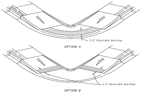
The detectable warning width is measured from the back of curb line on the ramp towards the top of the ramp.
Click to select the desired location of the detectable warning (for reference, see examples below).
This is measured from the top of the gutter edge.
This check box will change the counter slope of the gutter to match the slope of the ramp.
The retaining wall width is measured from the front to the back of the retaining wall.
This is the radius at which the retaining curb touches the flowline geometry.
This is the distance between the sawcut line and conform line on the left side of the curb ramp.
This is the distance between the sawcut line and conform line on the right side of the curb ramp.
If the ramp is not located perpendicularly to the curb, there is a triangular area between the detectable warning and the curb called a wedge. To make the slope of the wedge different than the slope of the ramp, select the check box and specify the desired values for the wedge elevation points.
Specify the points step size to coarsen or refine the curb ramp surface that is generated.
Select this check box to turn off the display of the elevations and slope arrows.
Select this check box to draw a surface of the curb ramp.
MicroStation users see Select Model Dialog Box below.
Note: The elevation of the back of the sidewalk is interpolated based on the intersection of the back of the sidewalk line and the back end feature line. Otherwise, it is calculated based on the DTM (Digital Terrain Model), if available. If that is not possible, the elevation of the nearest point on the back end feature line is used.
Select this check box to edit the vertical and horizontal offsets of the primary geometry to the secondary geometry.
This is the vertical offset distance from the primary geometry to the secondary geometry.
This is the horizontal offset distance from the primary geometry to the secondary geometry.
Select this check box to draw all available slopes and elevations for the selected curb ramp.
Select this check box to include the x,y coordinates in all elevation point callouts.
While in the Edit Curb Ramp dialog box, grips will display on various lines or endpoints which can be used to change values in the dialog box.
| Grip | Option | Click to... |
 |
Cyan square | Edit aspect with detailed grips and/or the dialog box. |
 |
Green square | Select replacement geometry. |
 |
Magenta diamond | Adjust along an axis (i.e. a stretch/shrink action). |
 |
Blue circle | Move a point anchor in any direction. |
 |
Blue triangle | Move a point anchor along geometry. |
 |
Magenta triangle | Adjust an angle. |
 |
Blue double arrow | Adjust a width or length, i.e. the ramp width or ramp length depending on the ramp type. |
 |
Cyan circle | Change an elevation value (VPI). |
 |
Green plus | Add a VPI. |
This dialog box is only available in MicroStation CONNECT editions. It displays when Generate Surface is selected in the Edit Curb Ramp dialog box.
Select one of the MicroStation models to draw the surface into.